Basic images
- L1R : Images with radiometric correction applied by KARI
- L1G : Images with geometric correction applied for L1R using orbit information by KARI
한국항공우주연구원(위성관제 및 원시영상수신, 기초 검보정 및 기본 영상 생산)에서
국토지리정보원(촬영계획수립, 기본영상수신, 각종 활용 산출물 생산 및 서비스)으로 기본영상 전달
국토지리정보원에서 한국항공우주연구원으로 좔영계획 전달
Calibration for production of basic images
- Raw data
-
방사보정, 대기보정, 기하보정 설명 Radiometric correction Geometric correction Radiometric correction enhances the accuracy of the pixel values by addressing distortions caused the sensitivity of the satellite sensor over time or across its field of view can affect the image data. Geometric correction overcomes the distortions in the geometric relationship between the sensor and ground objects due to Earth's rotation, Earth's curvature, and satellite orbital errors. -
Basic images
(L1R and L1G)
Corrected images
- Improved position accuracy (dozens of meters to several meters), improved spatial resolution (2m to 0.5m)
- Precisely corrected images (L2R): the images with precise geometric correction applied for L1G using GCPs
- Satellite orthoimages (L2G): the images with orthorectificaion applied for L2R by eliminating relief displacement and aligning each pixel's coordinates using DEM
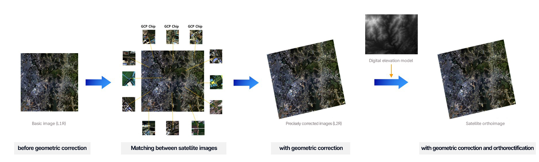
Process of orthorectification
융상융합(←L1R Product)→
GCP 자동매칭(←GCP chip)→
정밀기하보정(→L2R Product)→
(DEM DB→)정밀정사보정(←L2G Product)
Introduction to GCP chips
- Reference points in image format used for the automatic geometric correction of satellite images
- Constructed from aerial orthophotos cropped to a certain size around national official GCPs
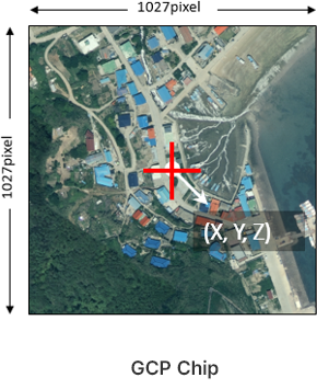
| Item | Description |
|---|---|
| Chip number | ID number of GCP chips |
| Ground coordinates | National unified GCPs |
| Ground coordinate representation | Latitude, longitude, and altitude |
| Data source | Aerial orthophotos |
| Chip size | 1027×1027 pixels |
| Spatial resolution | 0.25m |
| Spectral bands | Blue, Green, and Red |
Geometric correction of CAS500 images using GCP chips
Basic plans for national GCP chip construction
-
01. Construction and standardization plans
ACT 1 GCP Chip construction plans for CAS500 images
ACT 2 Preparation for the standardization, shared utilization, and legislation of GCP chip construction
-
02. Database construction and update
ACT 3 GCP chip database update for CAS500 images
ACT 4 Various GCP chip construction nationwide
-
03. System development
ACT 5 System design for automated construction of GCP chips, QA, distribution, and maintenance
ACT 6 System implementation
-
04. Governance
ACT 7 Operation of and inter-organizational initiative for GCP chip utilization
ACT 8 Establishment of international cooperation for GCP chip construction for CAS500 images
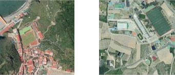
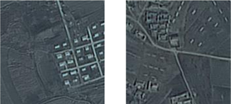
Introduction to national GCP chips
GCP chip specification for orthorectification
| Item | South Korea | North Korea |
|---|---|---|
| Ground coordinates used | Unified control points, photo control points, and triangular control points | Photo control points |
| Data source | NGII aerial orthophoto | Satellite images |
| Coordinate reference system | GRS80 / UTM-K | GRS80 / UTM-K |
| Spectral bands | Blue, Green, and Red | Panchromatic |
| Spatial resolution | 0.25m | 0.5m |
| Image size | 1027×1027 pixels | 513×513 pixels |
| Quantity | Approximately 25,000 | Approximately 25,000 |
| GCP chip example |
 |
 |